
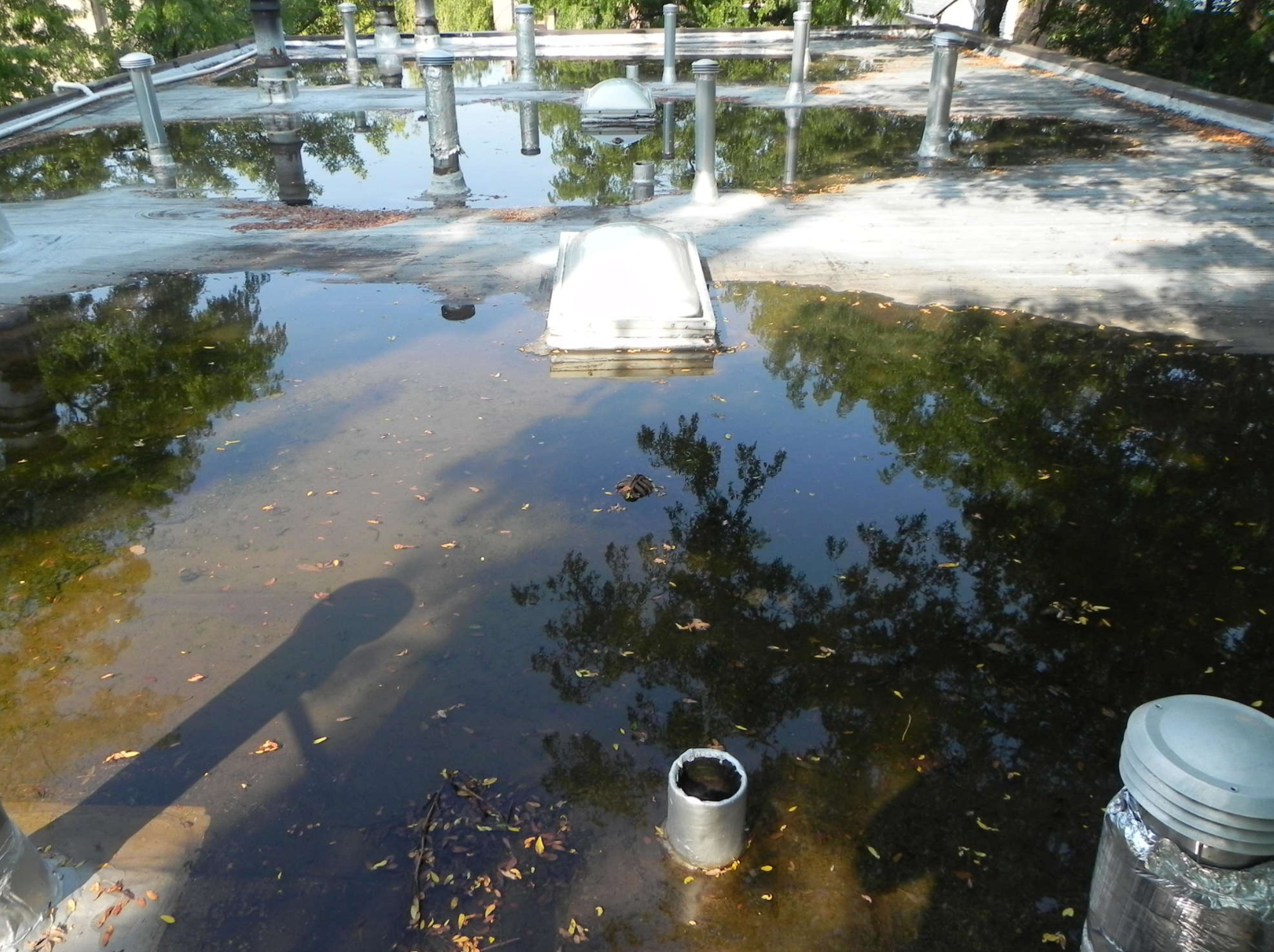

Photo 1. Roof decks with poor slope, drains that are up slope and deck defection can result in excessive ponding. Images: Hutchinson Design Group Ltd.
The stone church in rural Portugal was constructed some 700 years ago. The roofs of the transepts are large stone slabs: 5 feet wide, 10 feet to 12 feet long, and 8 inches thick. How they even made it into place is amazing, but to those like us who think in terms of water, what is even more amazing is the carved-out drainage channels. Moving water off the roof was important to builders 700 years ago in Europe, just as it was to the builders of Machu Picchu and Angkor Wat. Along with many indigenous building methods, the movement of water off roofs and away from buildings is becoming a lost design element.
It is not uncommon to walk upon recently installed roofs and see ponding at gutters, roof drains and across the roof. There are many reasons for this degradation of roof system design, including ignorance. A lack of knowledge by designers, a “roofer or builder will figure it out” mentality, and poor installation procedures can all be to blame.
Ponding water provides visual evidence to the owner that something isn’t quite right, and in some instances, it can result in roof structure collapse. If breaches in the roof membrane exist, standing water can result in excess moisture intrusion. (See Photo 1.) Additionally, water on the roof promotes algae growth that can attack some materials. It also allows for ice to form in winter, creating life safety issues as well as external forces affecting the roof cover.
So, what can you do?
In this article we’ll look at four key conditions on the roof that I see as the most erroneously conceived and installed:
- The roof system’s transition to the gutters
- Two-way structurally sloped roof decks with roof drains above the low point
- Four-way structurally sloped roof decks with drains above the low point
- Roof drains on level roof decks with tapered insulation
Accumulated Debris at Gutters
As perhaps you know and will see within this article, there are many things that irk me; one is walking on a new roof and seeing a 3- to 4-foot wide swath of black accumulated dirt and airborne components in front of the gutter. This situation
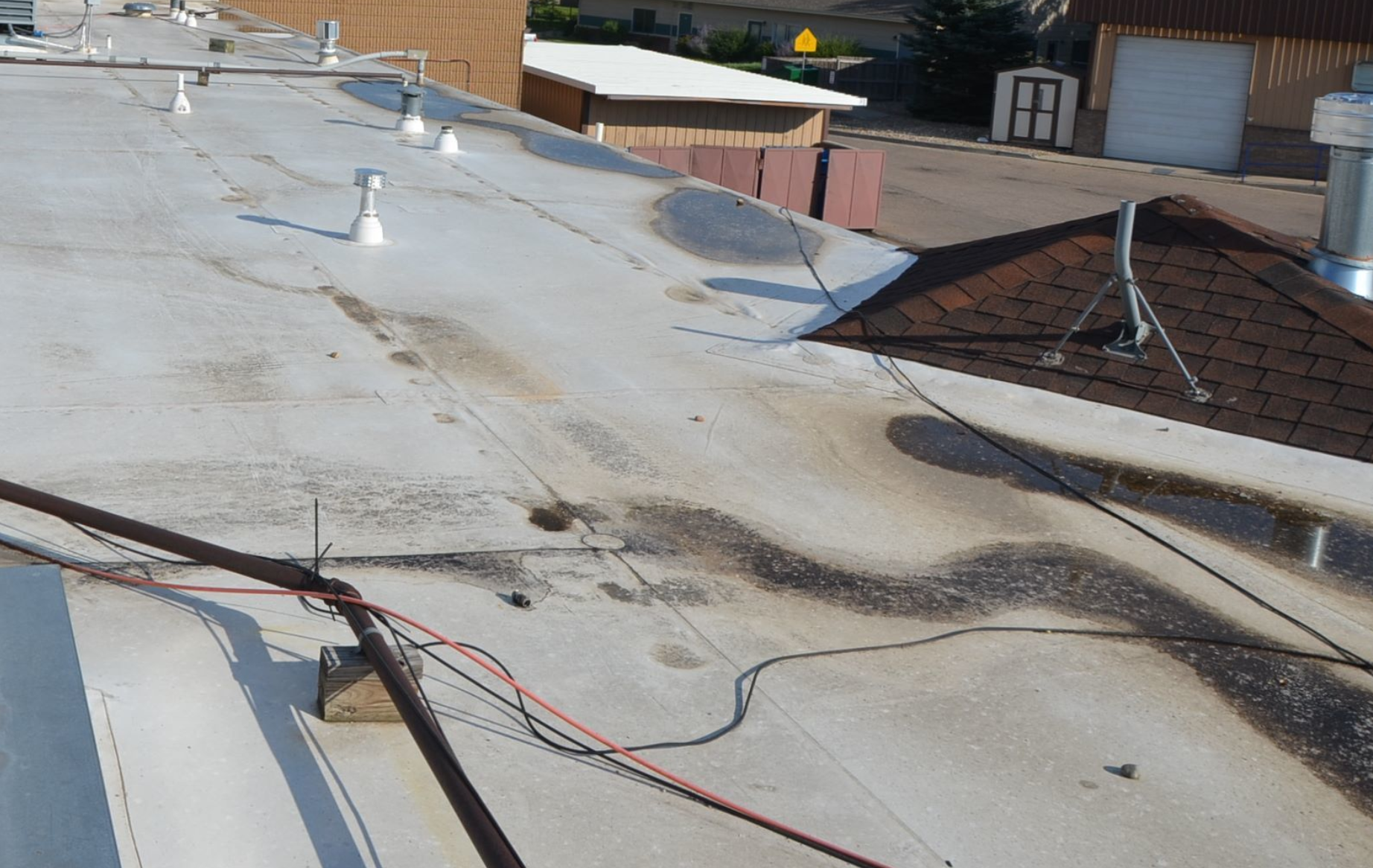
Photo 2. Owners do not like seeing ponding in front of their gutters, especially when it’s egregious. Proper design and installation would have prevented this problem. Images: Hutchinson Design Group Ltd.
results from restricted water drainage, and it is especially noticeable on reflective roof covers. (See Photo 2.) This restriction of water drainage can be due to several possible factors, including roof edge wood blocking that is too high, insulation that is too low, and the accumulation of roofing material above the slope plane. The roof deck itself can also be set too low.
When designing roof edge gutters, there are key design elements to consider:
- Wood blocking:In addition to being of appropriate width and anchorage, wood blocking should be sloped to drain, even with sloped roof decks with an elevation 1/4 inch to 3/8 inch below the anticipated roof insulation height. The greatest error I see with most architects is that they do not draw the detail to scale. Insulation is not of the correct thickness, the wood is too big or too small, or it is depicted as one giant block floating atop the wall with no mention of anchorage.
- Insulation:Please read the ASTM standard for polyisocyanurate and you will learn that the ISO has an allowable dimensional change. Thus, if you specified two layers of 2.25-inch ISO to match three layers of two-by wood blocking, you might be in for a surprise. You might get to the field and see that your two layers of insulation are 3/8 of an inch below the top of the wood, and the manufacturer whom you’ve complained to will pull out the ASTM standard and say, “We are within tolerances.”
- Material layering:When the roof membrane is taken over the wood (yes you should do this) and sealed to the wall substrate, and the gutter is set in mastic and then stripped in, the accumulated material thickness can exceed 3/8 of an inch. Not much, you say, but on a roof with a 1/4-inch-per-linear-foot slope, that can result in 18 inches of ponding right in front of the gutter. Ouch.
Design recommendations for achieving complete drainage at the roof edge with gutter include:
- Communicate with the structural engineer.Coordinate with the structural engineer to determine the elevation of the wall (less wood blocking) with the structure and roof deck. If perimeter steel angles attached to the wall rise above the roof deck, discuss with the structural engineer turning the angle downward or changing the angle to one with a vertical leg that doesn’t rise above the roof deck. Angles that rise above the roof deck create a void when

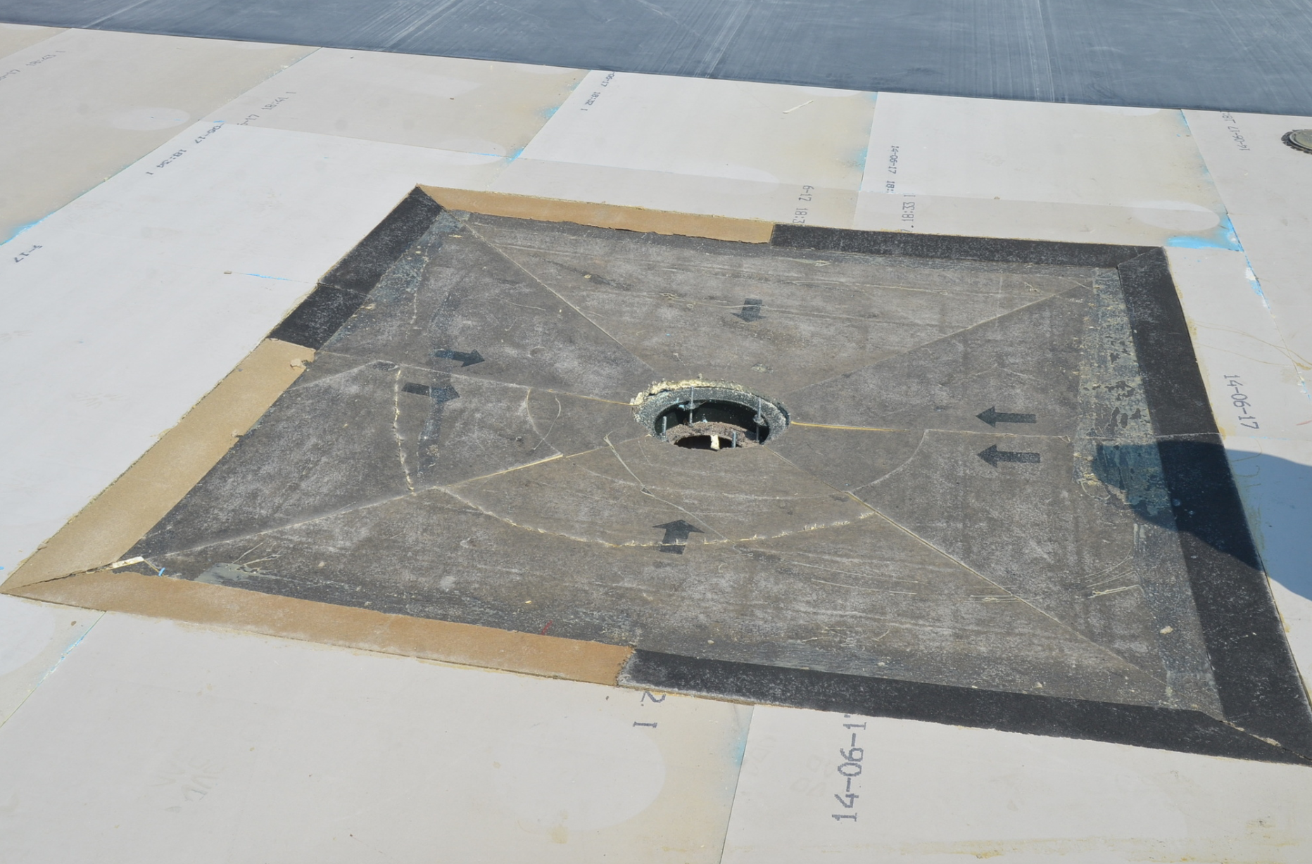
Photo 3. Even when using tapered insulation and on four-way sloped roof decks, it is advantageous to accentuate the slope into the drain. Here a 1/2-inch-per-foot tapered insulation sump matches up to the tapered insulation with the help if a 1/2-inch tapered edge strip. Images: Hutchinson Design Group Ltd.
the first layer of insulation is set that is most often not sealed, resulting in a thermal short and a place where dew points can be reached and condensation can occur. If reinforcing paper facers are on the insulation, mold growth can result.
- Properly detail the wood blocking. I prefer and recommend the use of two layers of wood blocking. First off, do not use treated wood; use untreated Douglas fir. The wood should be at a minimum 8 inches wide (preferably wider) so that the gutter flange can have nail locations back far enough to allow for 3-inch minimum overlap on the stripping-in ply.
Often it is best if the top of the wall is sealed prior to the installation of the wood to prevent air/moisture transport to the wood, and on precast, to prevent the migration of “damp” into the wood. The first layer of wood should be anchored to the structure (wall or framing). While not always required, I prefer to set anchors at 2 feet on center, staggered. This spacing prevents the warping of the wood. The second layer of wood should match the first in width. I suggest that this second layer of blocking be sloped, and placing a continuous shim along the roof side on the first layer will provide the proper slope. The shim width and thickness are dependent on the wood size, but for two-by-ten wood blocking, a shim of 1/2 inch by 1.5 inches will work well. The second layer of wood blocking should be set with joints offset from the lower layer and then screw fastened at 12 inches on center, staggered. Joints on both layers should be scarfed at 45degrees and screwed tight. On your detail, the height of the wood blocking at the interior side above the roof deck should be dimensioned. This will allow contractors to identify height concerns well before the installation of the insulation so adjustments can be made if necessary. I suggest that this distance be 1/4 inch to 3/8 inch below the top surface of the roof insulation or cover board atop the insulation. (See Figure 1.)
- Make sure the insulation is higher than the wood blocking.We will not discuss insulation types, substrate boards (vapor barriers) and cover boards in this article; please see earlier articles on the topic. In designing the roof edge and discussing/coordinating with the structural engineer, the goal is to have the insulation system: substrate board, vapor retarder, cover board. The thickness should be 3/8 of an inch greater than the interior top corner of the wood blocking. One key item to remember is that spray-and-bead polyurethane adhesive adds 3/8 of an inch thickness per layer. Designing the insulation to be higher than the wood blocking is important, as it compensates for that allowable dimensional change mentioned above, as well as the thickness created by the layers of gutter flange and roofing. The goal is to create a condition in which water will flow over and into the gutter.
Two-Way Structurally Sloped Roof Decks
Often long, narrow roof areas are designed with a two-way structurally sloped roof deck designed to move water from 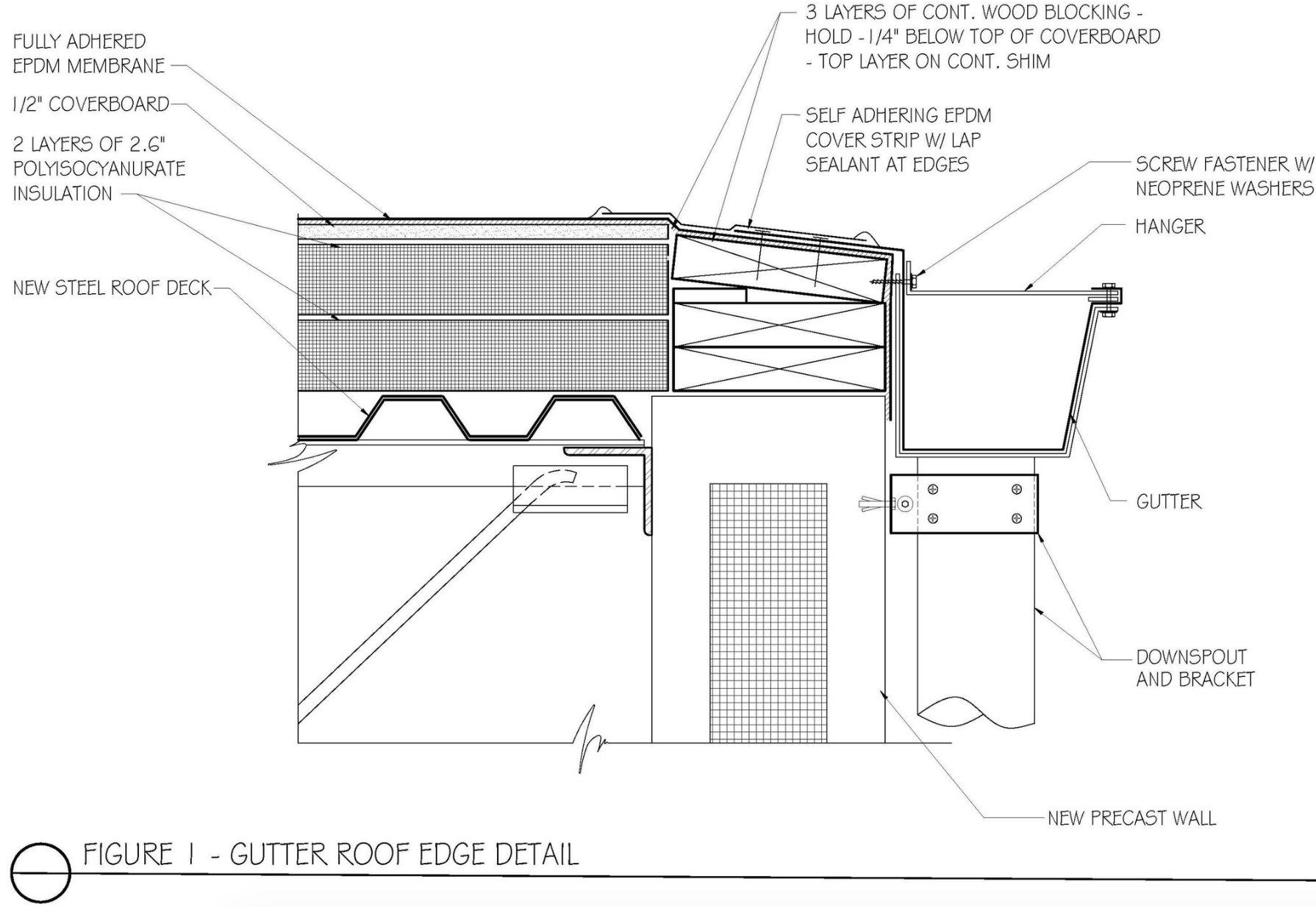 the outer roof edge to a central point. Prudent designers would like the roof drains to be located at the low point of the structurally sloped roof deck. Typically, though, there is a steel beam at the low point, which prevents the installation of the roof drain at the low point. Consequently, the roof drains must be located on the plumbing drawings up slope from the low point. I have tried for years to explain to plumbing engineers that water doesn’t typically flow uphill, but to no avail, so we as the roof system designer have to fix it. How? By moving the low point.
How is this design goal accomplished?
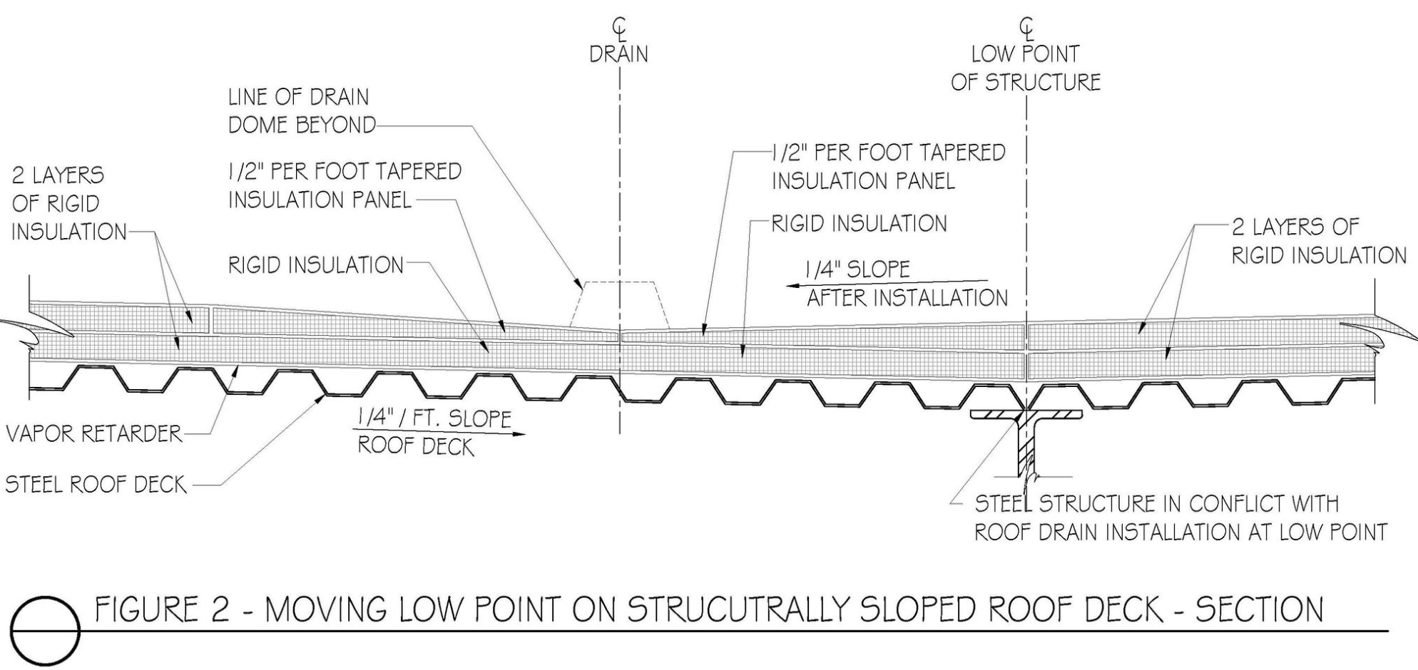
Let’s start with our roof system design for the following example: a new construction project in Chicago (R-30 minimum) with a steel roof deck, two-way structural slope and the low point over a steel beam. The plans call for the drains to be installed 2 feet up slope, and thus they will be more than 1/2 inch above the low point.
The goal will be to move the structural low point to the drain line. With a structural slope, to meet the thermal value we are looking at two layers of 2.6-inch insulation. Run the first layer of 2.6-inch insulation throughout the roof. Then the fun begins: Draw a line down the center of the roof drains. From this centerline, come out 4 feet on each side with a 1/2-inch-per-foot tapered edge board (Q panel, for those who know). The next layer of 2.6-inch insulation abuts the taper. The tapered insulation at the drain line effectively moves the low point to the drains. (See Figure 2.)
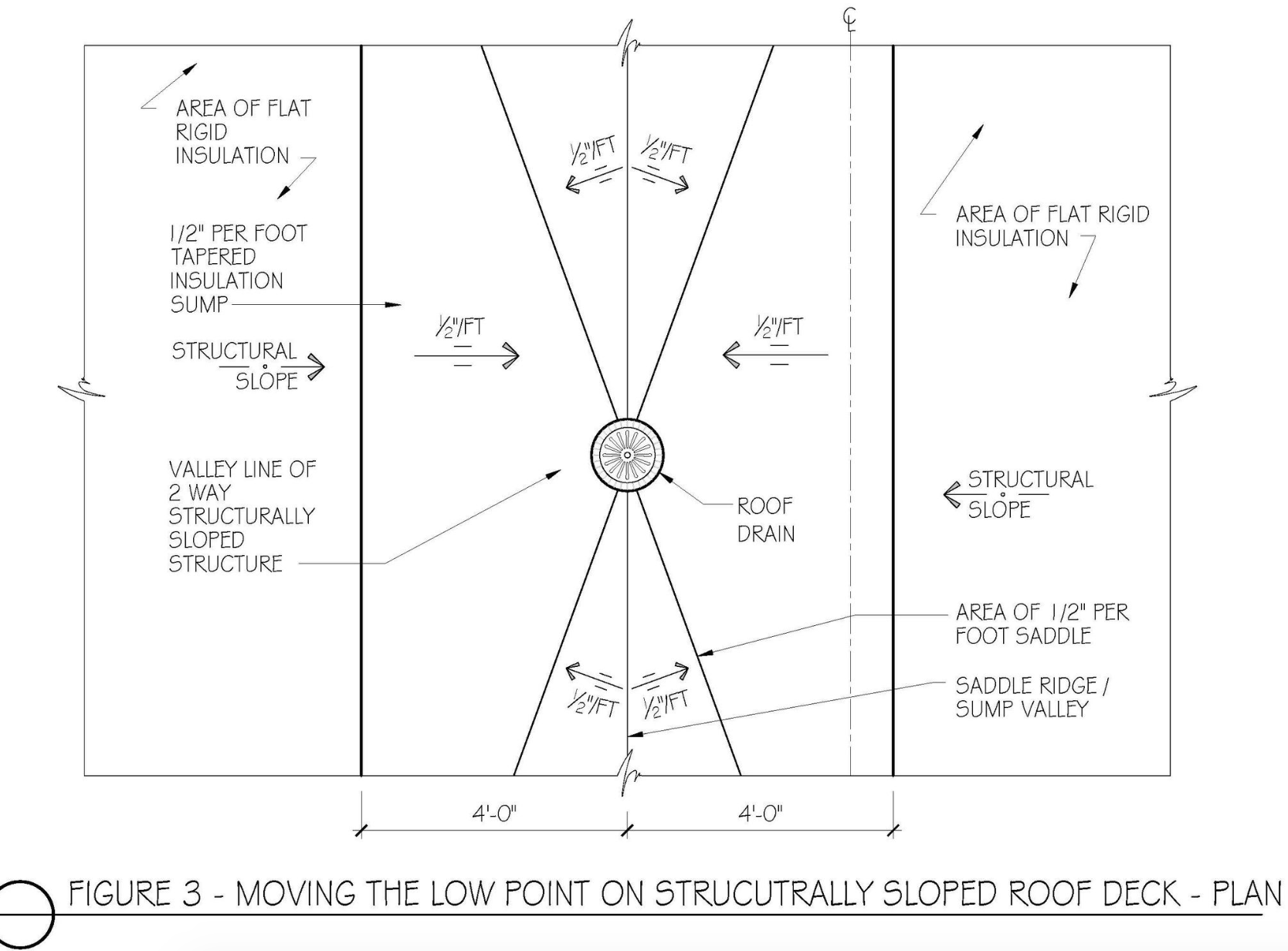
Now that the water is being moved to a new low point, it then needs to be moved to the drains. This is accomplished by saddles. (See Figure 3.) Sounds simple enough, but 95 percent of the saddles I see are incorrect, and water ponds on them, over them and along them. This situation leaves, once again, a bad taste in the mouth of the owner, general contractor, construction manager, and architect — even though it’s the designer’s problem. So, I will now, for the first time, reveal my secret developed years ago: The taper of the saddles mustbe twicethe roof deck slope. If the deck slopes 1/4 inch per foot, the saddles must slope at 1/2 inch per foot. If the deck slopes at 3/8 inch per foot, as it often does, the saddle needs to be at 3/4 inch per foot. And, architects and designers, the slope of the saddle is to the valley line, not the drain. The width of the saddle is the key and determining the width of the saddle is my secret.
It’s a simple formula:
(Distance Between Drain)x 33% = X
2
Increase X to the next number divisible by 4
Example: If the drains are 60 feet apart, divide 60 by 2 to get 30 feet; multiply 30 feet by 33% = 9.9 feet. Increase 9.9 to the next number divisible by 4 to get the answer: 12 feet.
 Thus, the saddles at the mid-point apex should extend out three full tapered insulation boards. It’s best if you dimension this width on the detail.
On large buildings, the saddle width and thickness can be quite high, so be sure to double-check the insulation height with the height of the roof edge. I could tell you about a roof where the insulation rose several inches above the perimeter height because someone didn’t draw the detail to scale, but that is a story for another time.
Roof Drains in Four-Way Slope Roof Decks
Structurally sloped roof decks can be beneficial in that they can create positive drainage flow. But with four-way structurally sloped roof decks, the drain is not necessarily at the low point of the roof. How far off the low point is dependent on the plumbing contractor. I have seen drains installed several feet upslope. The plumbing drawings should have a note to the fact that the roof drain sump pan should be installed as close to the low point as possible.
Even when the drain is installed very close to the low point, it is still high and will result in water ponding in front of the drain. Thus, the low point needs to be artificially moved to the drain.
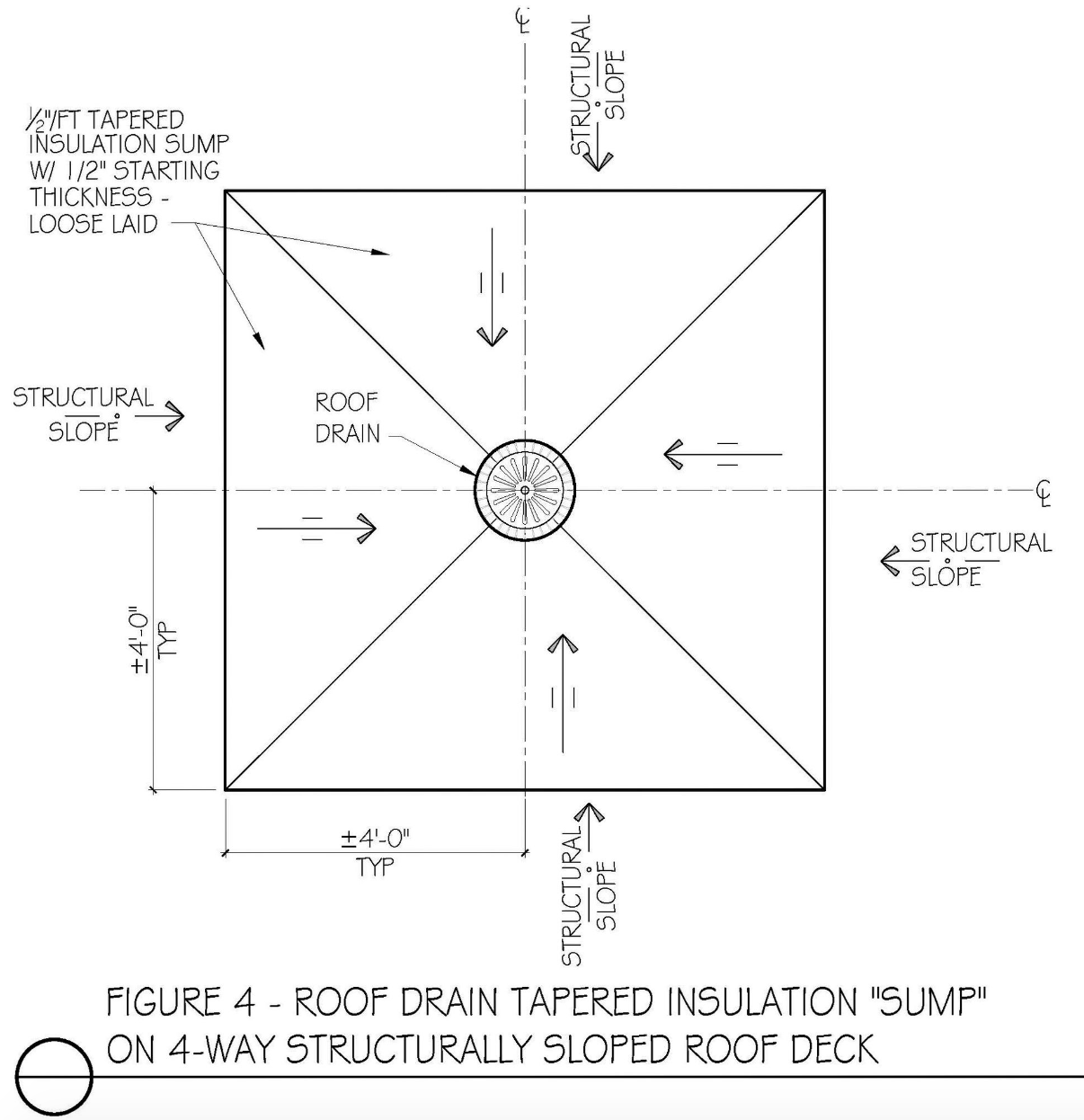
This is accomplished with a drain sump. Best practices suggest that the roof insulation be installed in two layers. This will allow for the installation of the sump.
Using Chicago as an example, which calls for R-30 or 5.2-inches of insulation, the first layer of insulation 2.6 inches thick is installed across the roof deck, to the roof drain. It should be cut to the roof drain extension ring. Fill the void between the roof drain and the insulation with spray foam; trim to the insulation. Next the tapered insulation sump is installed. To match the next layer of insulation, we use 1/2-inch-per-foot tapered insulation. It starts at 1/2 inch and, with a 4-foot panel, rises to a thickness of 2.5 inches. Placed around the drain, the sump created is 8 feet by 8 feet. The next layer of insulation is 2.5 inches and abuts the backside of the tapered insulation.
The 1/2-inch-per-foot slope is used as it doubles the slope of the structurally sloped roof deck, which in this case has a slope of 1/4 inch per foot.
Level Roof Decks With Tapered Insulation
 Whether re-roofing or new construction, getting the drainage correct on level roof decks is still a challenge for most designers. Perhaps they don’t realize decks are not level; they have camber, they deflect, they undulate, and the drains are often near columns so the drain pipe can run along it. When the drain is near a column where no deflection takes place, it can often be high.
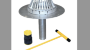
I like to first ensure the proper drain assembly has been selected and designed by the plumbing engineer: the roof drain, reversible collar, threaded extension ring, clamping ring, cast iron dome. (For more detail, see “Roof Drain Installation Tips” on page XX of this issue.) The sump pan should be selected and designed by the plumbing engineer and provided by the roof drain manufacturer — not by the metal deck supplier. (That the industry cannot get this correct is one on my pet peeves.) Do not raise drains off the deck with threaded rods. (See my article “Concise Details and Coordination Between Trades Will Lead to a Quality Long-Term Solution for Roof Drains,” RoofingMay/June 2016). If designing in a vapor retarder, it needs to extend to the roof drain flange and be clamped by the reversible collar. The first layer of insulation should be cut to fit and extend under and to the extension ring. Any voids should be sealed with spray foam.
To compensate for all the potential deck irregularities, I like to accentuate the slope into the roof drain by increasing the taper. More often than not, this means designing a 1/2-inch-per-foot slope sump into the drain. With a 4-foot board, this results in an 8-foot-by-8-foot sump. (See Figure 4 and Photo 3.) After detailing this sump, the main roof four-way tapered insulation can be designed and the heights at the perimeter calculated and noted on the plans. Just a reminder that the code-required thermal value needs to be attained four feet from the drain. So, for Chicago we detail to achieve R-30 at the backside of the tapered sump.
Final Thoughts
 A new roof installation that results in ponding water at the drainage point is an unfortunate occurrence. Owners can be upset: “What is that?” “I didn’t pay to have water retained at the drains!” “Who is coming up and cleaning all this stuff off my roof?” Ponding water can be a standard of care issue for designers and result in damages. Learning to properly design rooftop drainage is not difficult, but it requires some thinking and some rooftop experience. Getting up on the roof during installations will help you visualize the needs to achieve proper drainage.
Making sure the roof system drains properly requires discussions with the structural engineers for new construction. I also find it helpful to have the plumbing contractor at pre-con meetings to review the interrelationship of the roofing and drains.
Getting water off the roof as quickly as possible has been a key priority for centuries — no matter the roof cover material. If the builders using stone can achieve complete and full drainage, then I challenge you to achieve it with the materials we use today.

Regarding restricted water drainage, what are your thoughts on ballasted solar PV systems? I’ve seen lots of debris accumulate at the edge of the slip sheets they are installed on, keeping moisture trapped from decaying organic materials as well as undermining them with dirt granules as the system expands and contract each day. Also, finding a leak becomes extremely difficult. Would you recommend penetrated and flashed mounts rather than ballasted?