
Way back in the winter of 2000 in the northern United States, the snows were heavy and repetitive, resulting in a substantial amount of snow accumulation on roofs — and millions of dollars of damage to buildings. Complicating that issue was a great deal of misunderstanding among architects and contractors with regard to ice damming and its resultant water backup, eave ice accumulations, snow accumulations, and the potential for personal injury and property damage.
This two-part series proposes to take a practical approach to reviewing these issues across a number of steep-slope roof systems: asphalt shingle, slate, clay tile, wood and metal. Part 1 details the problems that can result from snow accumulation and outlines key design considerations. Here in Part 2, the author offers recommendations, suggested details, and examples of successful ways to prevent water intrusion into the roof system.
Prevention and Control

One unique property of snow and ice conditions is that, at times, it is a proper design consideration to try and control a condition known to occur rather than trying to prevent it from occurring. Depending on a building’s type, location and climate, it will be up to a roof system designer to use this knowledge, experience and perception in making these types of discretionary design decisions.
In the next section of this article, the prevention and control of the following conditions will be discussed: ice dams, snow sliding and falls, and icicles. Roof system designers are encouraged to thoroughly review building design, geometry, roof system design considerations and budget constraints prior to committing to a method of prevention and control.
Ice Dams
The occurrence of ice dams on residential homes in the United States is so commonplace and, at times, problematic, one would think design practices would have evolved to successfully prevent them from occurring or to least control them. The current standard practice is to provide some semblance of attic ventilation and to utilize ice-dam protection waterproofing membrane. When these methods are not thought out and well implemented, the result is moisture intrusion during periods of heavy snow and ice accumulation. As previously mentioned, a main concern is that roofs are not designed for snow accumulation totals as recommended by the author.
Incorporating full eave and ridge ventilation into an attic is the initial step in minimizing snow melt and its resultant ice buildup. Gable ends, dormers and attics utilized as living spaces complicate this design element. Incorporating a well-installed, quality air/vapor barrier in association with sufficient thermal insulation also is a must. Err on the side of conservatism and provide great amounts of insulation. It’s imperative all penetrations be sealed to the air/vapor barrier and that the air/vapor barrier at exterior walls be properly transitioned and sealed. Access panels to the attic should also be insulated and have vapor seals.
Additionally, all interior ventilation plenums, such as kitchen and bathroom exhausts, must be ducted to the exterior and insulated. Taking these precautions will minimize but not eliminate the creation of ice dams, as exterior forces can be outside a designer’s control. Solar radiation, temperatures above freezing, etc., will also act to create snow melt and freezing near the eave.
Understanding that ice dams can be minimized but not eliminated will lead a roof system designer toward methods of control. As reviewed in Part 1 under “Design Considerations,” the use of self-adhered ice-dam protection waterproofing membranes is a common method. Installation coverage should follow the authors’ recommendations. It has become common practice by some to cover an entire roof deck surface with these nonpermeable membranes. Although this practice is appropriate for some special conditions or constructability purposes, roof system designers are cautioned to proceed carefully with this practice and fully study the effects of double vapor barrier construction. The entrapment of moisture within an attic is of great concern.

The use of metal roofing in a variety of designs and constructions can help control ice-dam buildup, too. Standing seams, Bermuda seams, and flat-seam constructions have all worked. The use of solderable metals, such as copper, is recommended for the sealing of joints assumed to be under water. The use of low-slope membrane systems for locations that can be anticipated to be within reach of ice-dammed water can also be utilized. Modified bitumen systems installed with mastics can have long service lives.
Technology has also entered the roofing realm. Proprietary heating systems such as heated shingles and heat-trace systems may be appropriate. Although such heating systems may be appropriate, it’s incumbent upon a roof system designer to become completely knowledgeable of the systems — and know their limitations, electrical requirements, attachment methods and service lives. It’s not uncommon to observe heat-trace systems that are hanging over an eave having been ripped from the roof by a snow slide, thus opening points for moisture penetration and requiring repair.
Snow Sliding and Falls
Designing conditions that prevent snow sliding and falls is so restrictive to the building design effort that it’s virtually a nonexistent practice. Designing buildings and roof geometries to control snow sliding and falls, directing them away from locations of foot and vehicular traffic, landscaping, and building components susceptible to damage, is not only prudent but highly recommended and advisable.
The first step to controlling snow movement on a roof is having a roof system designer recognize conditions that will lead to snow movement. Thus, appropriate design elements can be implemented and designed as part of a roof system rather than being attached to a roof at a later date.
If possible, allowing snow to slide off a roof to the ground or roof location appropriate to receive such a dynamic load is the most practical. Doing so removes snow that could later melt and contribute to structural loads, ice damming, icicles and ice cornices. Designing gables and walls to divert sliding snow away from locations of concern can assist in achieving this type of control.
When manipulating a roof’s form to protect life and property is not appropriate to the building design, controlling snow accumulation on the roof takes precedence. The concept to remember here is “prevent the snow from moving.” Historically the use of snow fences and snow guards needs to be incorporated into the roof system design. These are often seen on large slate and tile roofs. The number and location of these fixtures can be a rather inexact science, but if incorporating a manufacturer’s product, abide by its experience and recommendations. If incorporating a “designed fence” for instance, abide by quality construction and installation techniques, remembering that these fixtures are structural elements and must be fully capable of withstanding considerable loads. The author has had great success utilizing fully welded bracket construction and fence components of minimum .125-inch-thick 280 brass alloy plate and 230 brass alloy .75-inch pipe with a wall thickness of .114 inch. The brackets should be mechanically fastened to a roof structure with the roof system flashed around the bracket base. In no case should brackets be attached to just a roof deck unless the roof deck is structurally capable of withstanding the loads that will be imposed. Avoid transferring loads through a roof system.
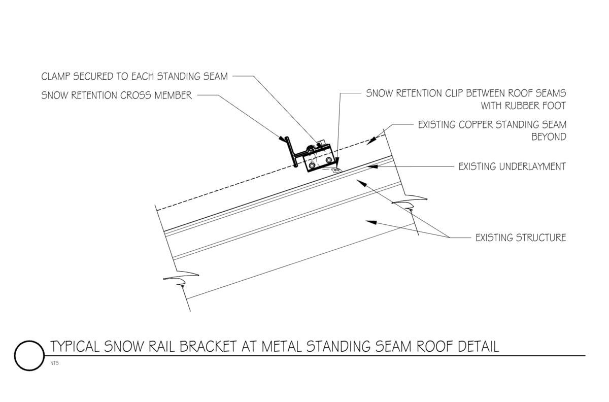
On metal roof systems, non-penetrating systems that clamp to the seams are preferred over a system that requires anchors to penetrate the roof panel and potentially restrict expansion and contraction. A fine example is the S-5! series of clamps and snow retention systems for metal roofs of different profiles. The company’s website (s-5.com) has good information on loading and a Snow Load Calculator for determining the number of rows of retention needed for a given project.
In locations that require extreme safety, fences of considerable height can be installed incorporating meshing to prevent the falling of snow and ice during periods of melt.
When conditions, design or retrofit applications require, snow fences that resist dynamic snow movement can be designed. These fences should have their structural elements designed by a professional engineer to resist anticipated dynamic loads. Fences can be designed to act as part of a slide guard system for roof maintenance and restrain loose or falling building materials. Intermittent fences on large roof surfaces can also be implemented. Traditionally, spacing of 25 feet has been used, but this is a function of loading, slope, bracket and bolt strength.
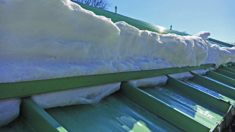
As reviewed previously, a roof’s slope and covering texture will affect anticipated snow movement, but the shear slippage between snowfall accumulations must not be forgotten. A past snowfall that has experienced some melt, has refrozen and resulted in a glazed-over top surface that is then covered with new snow creates a situation where the first snow is locked into the roof covering, but the new snow is held tenuously in place atop the first and may slide at any given moment.
When reviewing snow slides and falls, a roof system designer must, at all times, remember that the condition he is designing for can be life-threatening and take a conservative and precautionary thought process in the design of the preventative and control methods.
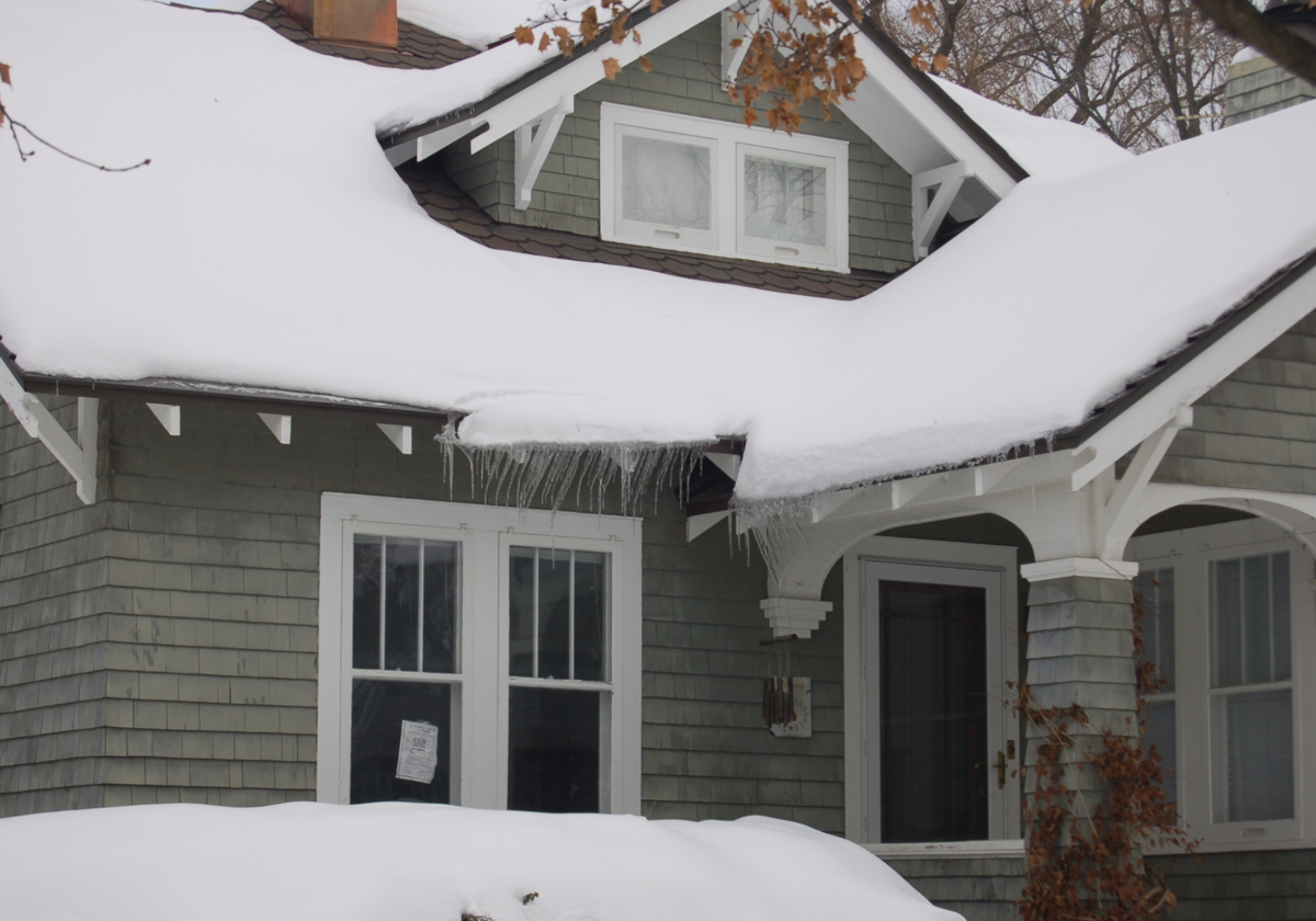
Icicles
Of all snow and ice conditions, icicles, ice columns and overhanging ice cornices seem to cause the most concern. This concern is for good reason because the thought of dagger-sharp stalactites overhead is not a comforting one. Unfortunately, overhanging ice is a characteristic of snow regions. As with ice-dam conditions, a roof system designer may be able to minimize the conditions that lead to icicle formation, but ultimately Mother Nature will prevail. At some time, icicles will form.
As reviewed under “Ice Dams,” incorporating substantial ventilation, thermal insulation and a quality vapor/air retarder is an essential beginning to prevent icicle formation. These types of prevention techniques are considered passive design elements.

Another passive approach that has been utilized successfully for years in snow regions prior to the use of the products developed to overcome design shortfalls is metal roof coverings at the eave in association with the main roof covering of choice. The author successfully incorporated a copper Bermuda seam roof panel 5-1/2 feet upslope from the eave. Enormous icicles and ice cornices have since been eliminated in all but the most severe conditions. Even then within the first few days of melt, the small accumulation of ice is removed from the roof.
Building design and roof geometry can also be utilized to minimize this concern. Eliminating eaves above pedestrian and vehicular traffic or protecting such traffic by use of dormer gables is effective. By not incorporating gutters into a roof edge and designing in eave drips whenever possible, a designer can also prevent future gutter damage and minimize the formation of large icicles. Taking a more active approach involves heating systems for use in the gutters, conductor boxes, downspouts below metal flashing, and along the roof eave utilized as individual solutions or in conjunction with one another. Glycol systems have been successfully incorporated into the substrate under large gutters and saddles. These systems involve the same elements used in heated floors or walkways and driveways.
Heat trace can also be incorporated into a roof edge design, but this takes well-thought-out design to be successful. The objective is to control the melted water and keep it liquid as it travels from the roof edge area where it may refreeze down to a ground level drain area or sewer. First, the heat-trace cable should be of an industrial size and function, be wired directly to power, and function on humidistats and thermostats. The industrial size cables will melt an area out from the cable of approximately 2 inches to 3 inches. This 4- to 6-inch area of melt around each cable requires that the cable pass itself every 12 inches or so. As a result, a great deal of back-and-forth is required. Downspouts should include passes down the pipe to grade or below into subgrade drainage pipe systems to an elevation of 12 inches beyond the frost line and then back up.
Another challenge of installing a heat-trace cable is securing the cable to roof coverings, gutters and downspouts without jeopardizing the waterproof integrity of the roof system clips attached to the roof deck. The connection needs to successfully resist the pull of snow slides from above, and ice locked around the cable during periods of intense cold will tend to pull on the connection.
The long-term performances of most heat-trace systems are not in line with the service lives of the roof coverings. With its inherent shortcomings and potential for jeopardizing a roof system, it is the author’s recommendation heat-trace cable systems be utilized as a last resort.

Many existing structures were built with no thought given as to how the roof systems would function under severe snow accumulation. Incorporating solutions to prevent and control snow and ice within a roof removal and replacement scenario and a given budget can be challenging and require innovative solutions.
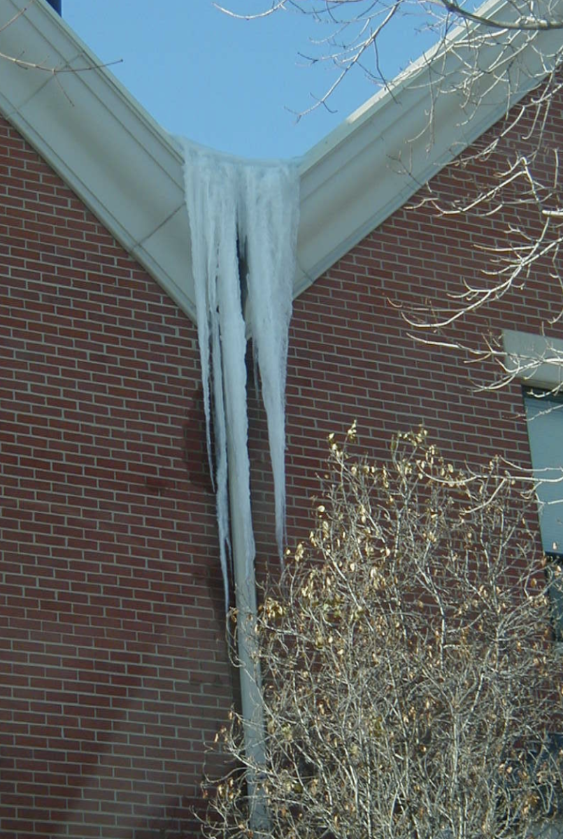
One project in Chicago found adjacent gables and three slopes draining to a small conductor box that was located within 3 feet of front entries and garage entrances. Following the snowfalls of December 2000, the ice formations above the conductor box were more than 2 feet thick, and ice-encased downspouts extending more than 25 feet were up to 18 inches in diameter. In addition to interior leaking, the ice columns facilitated moisture penetration through many windows, and the ice columns created life-threatening situations.
The solution to prevent interior and exterior moisture penetration and the creation of water overflow and resultant ice column was restricted by budget constraints that did not allow for redesign, enlargement and installation of new conductor boxes. Heat-trace systems were deemed to be too expensive and inappropriate for this application.
The solution involved a three-part design. First, it was known that substantial snow and ice accumulated at the confluence of the three roof slopes and two valleys. This snow and ice resulted in large amounts of water being held on the roof, which were backing up under the asphalt shingles. This was considered a water retention situation and produced concern. As such, a low-slope roof material, EPDM, was designed to be installed in this area and to extend upslope 18 inches beyond the maximum anticipated height of the water. The transition to the new asphalt roof system involved the installation of a copper transitional flashing piece set in mastic compatible to the EPDM membrane and nailed with ring-shank copper nails at 8 inches on center through staggered predrilled pilot holes. The top of the copper transitional flashing was primed and stripped in with a self-adhering ice-dam protection membrane that was extended another 6 feet upslope. No. 30 roofing felt, starter and field shingles were then installed.
The final design element was the installation of an ice-dam wall. This wall was constructed at the conductor box location. At the bottom, a 4-inch-by-12-inch scupper was created. The wall height was determined by the maximum anticipated snow accumulation, in this case approximately 3 feet. The entire wall was constructed on the ground and composed of 2-by-4-foot framing and 3/4-inch plywood. The top cap was left off for final attachment. Prior to installation, this wall was clad in EPDM. Set in mastic, the wall was bolted to the existing structure and the cap 2-by-4 set and clad in EPDM. The exterior side was faced with metal standing-seam siding and coping; the interior EPDM was left exposed. Subsequent snowfalls have shown the solution to be performing exactly as anticipated.
This case exemplifies the thought and consideration that needs to be given to the prevention and control of snow and ice conditions on new construction and retrofitted work. Spending time and effort prior to construction will save time, defending oneself in court or, worse yet, apologizing for personal injury. Following are recommendations for the design of preventing and controlling snow, ice and water backup conditions.
Recommendations
1. Prior to roof system design, research and obtain site-specific historical climatological data with regard to snowfall accumulation amounts, wind, freeze/thaw cycles, and any other localized weather phenomenon that will affect and influence snow melt and ice creation.
2. Design for 100-year totals, including the total accumulation of all snowfalls across the winter as if there were no melting of the previous snowfall.
3. Consider roof slope and rafter length in the design analysis; steeper slopes and shorter rafter lengths are best.
4. When possible, use building design and roof geometry to prevent the creation of dangerous conditions.
5. Realize the importance of the “robust roof” and the use of quality materials.
6. Design roof coverings, underlayments, and ice and snow controls as a system, remembering that a roof is only as good as its weakest link.
7. Incorporate air/vapor retarders, thermal insulations and ventilation to minimize the effects of heat loss on snow melt.
8. Incorporate heating systems only as a last resort after all passive prevention and control concepts have been considered.
9. Observe and study existing roof systems during periods of heavy snow to understand and learn how snow behaves under various conditions.
10. Observe installation procedures to verify installation to design and specification.
11. Design in redundancies.
About the author: Thomas W. Hutchinson, AIA, CSI, Fellow-IIBEC, RRC, is a principal of Hutchinson Design Group Ltd. in Barrington, Illinois. For more information about the company, visit hutchinsondesigngroup.com.
Be the first to comment on "Designing for Snow, Water and Ice — Part 2"