
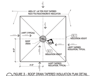
FIGURE 3: A roof drain plan with insulation heights is helpful in communicating the design intent to contractors.
ROOF SYSTEM INCORPORATION
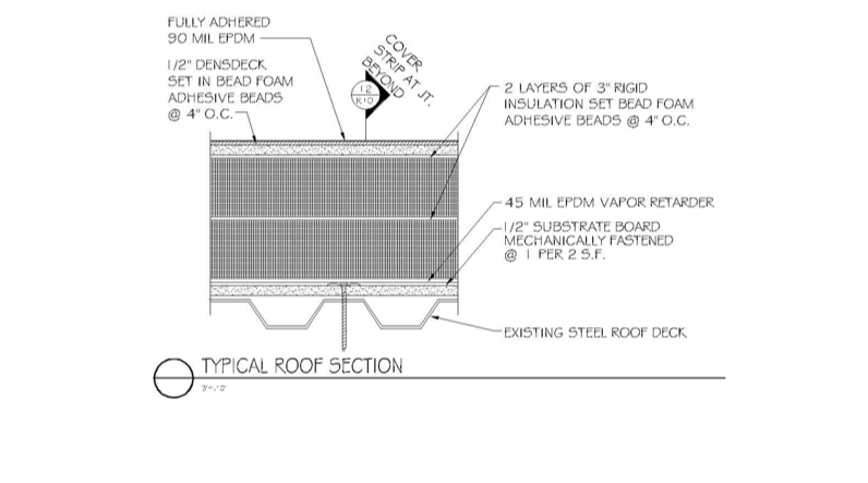
It is now time to design the new roof system from the roof deck up. Our example requires a vapor retarder on a substrate board. Thus, the first consideration of how the vapor retarder will be terminated to the roof drain needs to be considered. This is a vulnerable area for air infiltration and needs careful consideration and design.
For our hypothetical project, a substrate board is to be installed over the roof deck. It should be cut to the edge of the roof drain. Slight beveling of the substrate board is OK but not necessary. The drain flange should be cleaned of all foreign contaminants and coated with the manufacturer’s recommended primer/adhesive. The primer/adhesive should also be applied to the substrate board to ensure a quality bond of the vapor retarder, which is then installed over the roof drain flange out over the substrate board. The vapor retarder at the roof drain flange should be rolled with a neoprene roller to ensure positive contact.
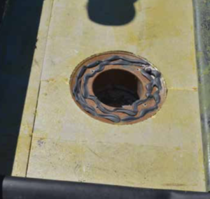
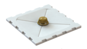
PHOTO 3: Here the roof drain extension ring is covered with water block over which the roof membrane will be installed. The clamping ring will compress the roof membrane into the water block and extension ring flange to create a watertight seal. Note the well-executed cover board cut tight to the edge of the drain flange and the threaded roof drain extension screwed down to be below the cover board.
Next, the vapor retarder should be cut to the vertical rise in the roof drain bowl. To ensure a seal and be able to install the threaded extension, the reversible collar is now clamping the vapor retarder. A threaded roof drain extension is required to make up the distance from deck up to the top of the insulation. This threaded extension will need to be screwed to a proper location (top of the insulation is recommended). To do so, the insulation below the drain will need to be slightly beveled. This should be shown in the detail (see Figure 2). A roof drain plan with insulation heights is also helpful in communicating to the contractors the design intent (see Figure 3). To prevent a thermal short, the void between the roof drain bowl and the insulation should be sealed with spray-foam insulation, which is allowed to rise and then cut back.
The designer now moves to the cover board, which should be drawn into the detail. I prefer to show the cover board cut vertically to the roof drain extension ring—NOT beveled (see Photo 3). The reason is, in the field, contractors like to place their handsaw under the flange of the extension ring and cut away. When they do this, two bad things happen:
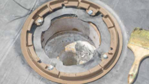
PHOTO 4: The roof drain extension ring can be seen and the top surface of the roof membrane is above the clamping ring, thus preventing ponding at the roof drain because of the thickness of the clamping ring.
- 1. The roof membrane surface will be below the roof extension ring elevation and with the clamping ring result in ponding water. Clients do not like ponding water at their roof drains.
- 2. The exposed cast-iron edge of the extension ring is now in contact with the membrane. A raw steel corner in contact with a roof membrane is not prudent and, after time, deck and membrane movement will result in wear on the underside of the roof drain, right where the water flows. You’re basically building a future water flow to the interior.
The membrane transition to the drain now can be designed. A single-ply membrane will need to be sealed at the roof drain extension ring flange. This is accomplished by using a full tube of water block (see Photo 3)—not a single bead, not a half a tube, but a full tube!
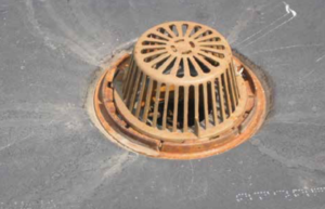
PHOTO 5: This is a well-executed roof drain and roof system installation.
Your detail is now complete, but your work is not. I repeat: I recommend your detail be shared with the plumbing and structural engineers with the request that they review the detail; modify their specifications accordingly; and place the detail in their respective sheets, ensuring coordination.
DETAILS AND COORDINATION FOR LONG-TERM SUCCESS
Roof system to roof drain intersections should always be designed. There are too many trades involved in coordination—in the design preparation of details and in-field installation—to be left to chance. The recent increase in thermal insulation and the requirements at the roof drain make this more challenging for many designers.
With thoughtful consideration, an understanding of all the disciplines and trades involved and the coordination between them all, including roof drain and roof system components, appropriate design can be achieved (see Photo 5). With clear and concise detailing, coordination amongst disciplines, a quality long-term solution can be achieved and the big bad bear of high levels of thermal insulation at the drain tamed.
PHOTOS AND ILLUSTRATIONS: HUTCHINSON DESIGN GROUP LLC
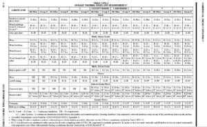
2012 IECC
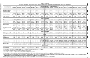
2015 IECC


If the sump and storm drain pipe is now insulated, in northern climates the snow and ice will not melt and block the drain. In a thaw the drain is frozen and the water can not drain from the roof, and re-freezes every night causing the structure to be over loaded. This is currently a common problem on some roofs where the roofing contractor cut corners and run the insulation near the drain bowl with a minimum sump.
The IECC needs to reconsider they zeal for energy conservation and let the drain melt away the ice and snow so it can drain.